Setup
Setup
1. Rust
Go to https://www.rust-lang.org/tools/install
💡 Windows users: prefer to install Rust natively, rather than using WSL.
2. Toolchain
To compile Rust code for out ESP32-C6 microcontroller, we need to install the appropriate toolchain.
rustup toolchain install stable --component rust-src --target riscv32imac-unknown-none-elf
3. Tools
Additionally, we will want tools to help us generate projects and program the firmware.
cargo install cargo-espflash espflash esp-generate
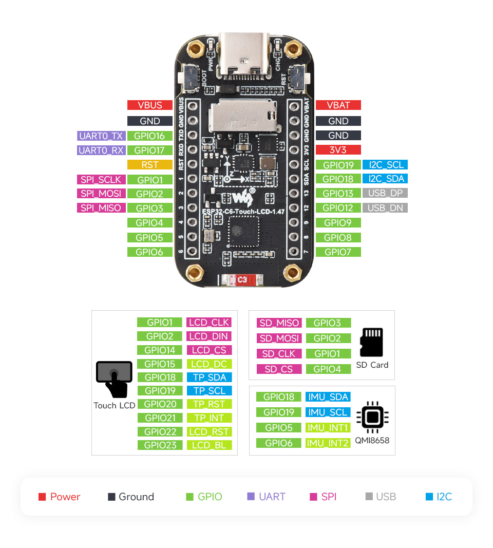
Hardware information
Board pinout
Documents
Links
Hello World
Create the project
Let's create our first embedded Rust project. For this, we will be using esp-generate tool installed earlier.
To begin with, run the following command:
esp-generate --headless --chip=esp32c6 -o log -o unstable-hal hello_world
This will create a new project in hello_world directory. Go ahead and open it with: code hello_world.
💡 You can run
esp-generate --chip=esp32c6to open the tool in interactive mode and explore the available options.
Run
With the ESP board plugged into your computer, you should be able to run the firmware with:
cargo run
You may have to select the appropriate device. If this is the case, the tool will prompt for it.
If everything goes well, your device will boot and start printing the "hello world" message:
INFO - Hello world!
INFO - Hello world!
INFO - Hello world!
INFO - Hello world!
INFO - Hello world!
Experiment
Experiment with this example a little bit.
- Change the message to print something else.
- Change the log level (e.g. to
warn). - Change the printing frequency by adjusting the sleep duration.
Delay
The way the delay is currently written is a bit verbose.
We can simplify the code by using Delay from the esp_hal crate.
Add the following line next to the existing use declarations:
#![allow(unused)]
fn main() {
use esp_hal::delay::Delay;
}
Create a delay variable:
#![allow(unused)]
fn main() {
let delay = Delay::new();
}
Replace the two lines using delay_start with the following one line:
#![allow(unused)]
fn main() {
delay.delay_millis(1000);
}
Panicking
When an unrecoverable error happens in Rust, the program panics. There are several ways that panics can be handled, but it usually ends up with your program exiting (crashing).
Let's try it. Add this before the "hello world" message:
#![allow(unused)]
fn main() {
panic!("Oh no!");
}
We should observe two things:
- Compiler gives us "unreachable statement" warning for the code after
panic!(). - When we run our program, it doesn't appear to do anything.
Let's fix point 2 by displaying the panic information. First, let's import error macro from the log crate:
#![allow(unused)]
fn main() {
use log::{info, error};
}
Then, modify the panic handler, located just after import statements, like so:
- Give a name to the
PanicInfovariable. In Rust, we use_when we have unused variables that we don't want to name. - Print the panic info using the
error!()macro.
#![allow(unused)]
fn main() {
#[panic_handler]
fn panic(panic_info: &core::panic::PanicInfo) -> ! {
    error!("{panic_info}");
    loop {}
}
}
Now, we get a useful message about why our program crashed:
ERROR - panicked at src/bin/main.rs:32:9:
Oh no!
Finally, don't forget to delete the panic!() call before proceeding to the next section!
Blinky
We have created a typical "hello world" application, but in embedded systems, the equivalent of "hello world" is blinky: simply blinking an LED.
We will continue working in the hello_world project.
Change the program
In order to blink an LED, we need to define an output pin and make a couple of other changes.
Firstly, let's rename the _peripherals variable to peripherals.
💡 In Rust, a variable can be prefixed with an underscore (
_) to indicate that it is unused. Since we'll be using it, let's remove the leading underscore.
Next, we will define our LED:
#![allow(unused)]
fn main() {
let mut led = Output::new(
    peripherals.GPIO19,
    Level::Low,
    OutputConfig::default().with_drive_mode(DriveMode::OpenDrain),
);
}
The code above will not compile as is, since the compiler won't know where Output and other types are coming from. To fix that, import the required types like so:
#![allow(unused)]
fn main() {
use esp_hal::gpio::{DriveMode, Level, Output, OutputConfig};
}
💡 Whenever a you have a missing declaration error, you can use
rust-analyzerto help you fix it.Place the cursor on the missing type name and press
Ctrl+.on the keyboard. In the context menu, selectImport <Type>orQualify <Type>."Import" will add the required
usedeclaration, while "Qualify" will prefix the module path in-place.
Finally, add the following line to the body of the loop to toggle the LED every cycle:
#![allow(unused)]
fn main() {
led.toggle();
}
Experiment
Output has other methods than toggle. Try using set_high and set_low methods to change the LED blinking pattern.
Exercise: working with inputs
We have worked through an example of driving a GPIO output. Now it's time for you to try and extend the program to read the GPIO input state.
- Use the
esp_halcrate documentation to create and initialize a GPIOInput. - The button is connected to
GPIO9. - Write a program that turns the LED on only while the button is pressed.
Solution
- Add new imports:
#![allow(unused)] fn main() { use esp_hal::gpio::{Input, InputConfig}; } - Declare the button:
#![allow(unused)] fn main() { let button = Input::new(peripherals.GPIO9, InputConfig::default()); } - Modify the loop code:
#![allow(unused)]
fn main() {
 if button.is_high() {
     led.set_high();
 } else {
     led.set_low();
 }
}
Explanation
You may be tempted to think that high means ON and low means off, however, the logic of both the button and the LED
is inverted.
Button has a pull-up resistor and connects the pin to ground when pressed.
The LED has its anode connected to the 3.3 V supply and the cathode is connected to the open-drain output. When the output is set to low, it is connected to ground, allowing the current to flow and thereby turning the LED on.
Interrupts
In the last exercise, we learnt how to read a GPIO pin state. However, it's not always desirable to poll the pin state in software. This is where interrupts come it. We can ask hardware to notify us whenever the pin state changes.
Background
Because interrupts can happen at any time during the execution of our program, we can think of them as if they're running on a separate thread. As such, when working with interrupts, we apply the same principles as when working in a multi-threaded environment.
Additionally, because the interrupt routine is called by hardware, there is no way to pass parameters or return values from the interrupt handler.
One common way to pass data between the application and interrupt contexts is using global state. This is mostly straightforward in C, as you can just read and write any global variable at any time. Whether you like it or not, this "feature" opens up questions about what happens when the variable is modified while some other code is reading it?
Consider this code:
volatile int counter = 0;

int main() {
    while (true) {
        app_task();
        ++counter; // Same as: counter = counter + 1
    }
}

void timer_interrupt() {
    interrupt_task(counter);
    counter = 0;
}
In Rust, however, using a mutable global state is explicitly unsafe. While it's possible to bypass
the compiler rules, the language strongly encourages developers to write correct code.
Atomics & Mutexes
When working with primitive types we can use one of the types provided in core::sync::atomic.
Atomic types are the most fundamental way to ensure exclusive access -- these opperations are provided by the CPU.
For more complex types, we have to resort to higher level synchronization primitives, such as Mutexes and
other types of locks. Note that Mutex is only available in the std library, as is requires operating system support.
No worries though, for embedded systems we can use Mutex provided by the critical_section crate.
GPIO Interrupt
Let's see how we can use interrupts on ESP32.
Declaring global mutable objects
At least in case of esp_hal, interrupt status is not cleared automatically, so we'll need to do that ourselves.
For that, we will need to access the button object inside the interrupt handler, so we have to make it global.
Additionally, since we will be modifying this global object, we have to ensure it's done in a safe way, without causing race conditions.
We'll need to wrap our Input with three different types, so this will be very confusing at first. The purpose of each
type will be explained at the end of this section.
Start by importing the necessary types:
#![allow(unused)]
fn main() {
use core::cell::RefCell;
use critical_section::Mutex;
}
Now, we can declare our global button:
#![allow(unused)]
fn main() {
static BUTTON: Mutex<RefCell<Option<Input>>> = Mutex::new(RefCell::new(None));
}
As you can see, our Input is wrapped in an Option, which is wrapped in a RefCell which in turn is wrapped
in Mutex.
Let's look into each one starting with the outermost.
Mutex
Mutex, when combined with the critical section, allows us to get an exclusive access to the stored type.
Unlike the Mutex in Rust's std library, critical_section::Mutex does not provide ability to mutate the
contained value. For this, we have to rely on the next type.
RefCell
In short, RefCell is a run-time borrow checker. When we call borrow or borrow_mut methods, the type will check
that the value is not already borrowed. If it is, we will get a panic. If we successfully get the mutable reference,
we can safely mutate the stored value, because we know that no-one else has any reference to our object.
Option
Option is required because we cannot create Input at the initialization time. We need to initialize the chip,
configure peripherals etc. Option allows us to initialize an "empty" object first and fill it later when we're ready.
Handler function
Next, let's look how we can define an interrupt handler function.
Import the handler macro:
#![allow(unused)]
fn main() {
use esp_hal::handler;
}
Then define the handler function at the bottom of the file, like this:
#![allow(unused)]
fn main() {
#[handler]
fn button_handler() {
    info!("GPIO interrupt!");
    critical_section::with(|cs| {
        BUTTON
            .borrow(cs)         // Borrow the value in Mutex
            .borrow_mut()       // Mutably borrow value in RefCell
            .as_mut()           // Get mutable reference to the value in Option
            .unwrap()           // Unwrap the Option<&mut T>
            .clear_interrupt(); // Clear the interrupt flag
    });
}
}
💡 To make things a bit more concise,
Mutexprovides aborrow_ref_mutmethod that combines theMutexborrow andRefCellborrow into one function. We will use that function from here on.
💡 Note how our handler function is marked with the
#[handler]attribute macro. We can usecargo-expandtool to expand the macros and see what code is being produced. Our handler function gets expanded to the code below:#![allow(unused)] fn main() { extern "C" fn __esp_hal_internal_button_handler() { // Function body goes here } #[allow(non_upper_case_globals)] const button_handler: esp_hal::interrupt::InterruptHandler = esp_hal::interrupt::InterruptHandler::new( __esp_hal_internal_button_handler, esp_hal::interrupt::Priority::min(), ); }
Setting up interrupts
Next, we can register our handler to handle the GPIO interrupts. Add this to the setup part of your main function:
#![allow(unused)]
fn main() {
let mut io = esp_hal::gpio::Io::new(peripherals.IO_MUX);
io.set_interrupt_handler(button_handler);
}
Finally, we start to listen to the button events and move the button object into our global state. We will use a "rising edge" event, which means that the interrupt will be triggered on button release.
Import Event:
#![allow(unused)]
fn main() {
use esp_hal::gpio::Event;
}
Add this code right after the existing declaration of button.
#![allow(unused)]
fn main() {
critical_section::with(|cs| {
    button.listen(Event::RisingEdge);
    BUTTON.borrow_ref_mut(cs).replace(button);
});
}
Experiment
Try changing the event type to falling edge. Do you observe any difference?
Exercise: toggle LED with interrupt
Now that we have set up the GPIO interrupt, try using it to toggle the LED. There are many ways to achieve this, so let's set some specific requirements:
-
Use
AtomicBoolWe have already seen how to use a Mutex, so for this exercise, let's try something new.
-
Toggle the LED in the main loop
In general, we want to avoid doing any work in the interrupt handler, so use the
AtomicBoolto signal to the main loop that the LED should be toggled. Remove any other code from the loop for now. -
Use
FallingEdgeinterrupt type -
Take care of debouncing
You will encounter switch bounce - several interrupt events occurring from a single button press. Try to come up with a solution for this problem so that the LED is only toggled once per button press. There are a multitude of ways to implement this so any solution that works is fine.
Solution
First, we'll need to import atomic and then declare our static object object.
#![allow(unused)]
fn main() {
use core::sync::atomic;

static BUTTON_EVENT: atomic::AtomicBool = atomic::AtomicBool::new(false);
}
Next, set the BUTTON_EVENT in the button_handler():
#![allow(unused)]
fn main() {
BUTTON_EVENT.store(true, atomic::Ordering::Relaxed);
}
Finally, in the main loop, let's check the BUTTON_EVENT and if it's true, toggle the LED.
#![allow(unused)]
fn main() {
loop {
    if BUTTON_EVENT.load(atomic::Ordering::Relaxed) {
        led.toggle();
        // Delay before resetting the BUTTON_EVENT acts as debouncing logic.
        delay.delay_millis(150);
        BUTTON_EVENT.store(false, atomic::Ordering::Relaxed);
    }
}
}
PWM
In this chapter, we will learn how to digitally control the brightness of the LED using Pulse-width modulation.
We will continue using the same hello_world project from the previous workshops.
esp-hal crate provides a PWM driver in mcpwm module. Let's start by importing the necessary modules and types:
#![allow(unused)]
fn main() {
use esp_hal::mcpwm::operator::PwmPinConfig;
use esp_hal::mcpwm::timer::PwmWorkingMode;
use esp_hal::mcpwm::{McPwm, PeripheralClockConfig};
use esp_hal::time::Rate;
}
Next, let set up the PWM peripheral:
#![allow(unused)]
fn main() {
let clock_cfg = PeripheralClockConfig::with_frequency(Rate::from_mhz(40)).unwrap();
let mut mcpwm = McPwm::new(peripherals.MCPWM0, clock_cfg);
let timer_clock_cfg = clock_cfg
    .timer_clock_with_frequency(255, PwmWorkingMode::Increase, Rate::from_khz(20))
    .expect("could not determine parameters for the requested frequency");

mcpwm.operator0.set_timer(&mcpwm.timer0);
mcpwm.timer0.start(timer_clock_cfg);
}
💡 Note the use of
expect.expectperforms the same function asunwrap, but allows us to write a helpful error message. In general, use ofunwrapis discouraged outside of "example" code. Ideally, the errors should be handled gracefully or at least, provide an explanation of what has happened.
We'll change the LED pin to GPIO16, so we can have active-high configuration:
#![allow(unused)]
fn main() {
let led = Output::new(
    peripherals.GPIO16,
    esp_hal::gpio::Level::Low,
    OutputConfig::default(),
);
}
Then, we will transfer GPIO to the PWM instance:
#![allow(unused)]
fn main() {
let mut led = mcpwm.operator0.with_pin_a(led, PwmPinConfig::UP_ACTIVE_HIGH);
}
💡 Note how we're re-using the name
led. This is called rebinding and allows us to write cleaner code.
Finally, let's modify our application to cycle through different brightness levels in a loop:
#![allow(unused)]
fn main() {
let mut sequence = [32, 128, 255].iter().cycle();
loop {
    led.set_timestamp(*sequence.next().unwrap());
    delay.delay_millis(1000);
}
}
Exercise: LED breathing effect
We learnt how to control the LED brightness and make the brightness ramp-up. For this exercise, you have to implement a commonly-used breathing effect.
The sequence is roughly as follows:
- LED brightness should increase gradually until it reaches the maximum.
- LED brightness should decrease gradually until it reaches zero.
- LED stays off for a couple of seconds.
- The sequence repeats.
Solution
The requirements of this exercise a suited perfectly for a state machine
and Rust's enums work great for state machines.
Let's define our enum. We can achieve our goals by using two variants (states): one for increasing brightness and one for decreasing. The enum variants will hold the actual brightness value.
#![allow(unused)]
fn main() {
enum LedState {
    Up(u16),
    Down(u16),
}
}
Let's create the instance of our LedState. Declare this variable just above the main loop:
#![allow(unused)]
fn main() {
let mut led_state = LedState::Up(0);
}
We will start at zero brightness and increasing direction.
Finally, let's implement our state transitions:
#![allow(unused)]
fn main() {
loop {
    match led_state {
        // We have reached maximum, change state to ramp down.
        LedState::Up(255) => {
            led.set_timestamp(255);
            led_state = LedState::Down(255);
        }
        // Ramping up: increment the brightness.
        LedState::Up(brightness) => {
            led.set_timestamp(brightness);
            led_state = LedState::Up(brightness + 1);
        }
        // We have reached minimum, wait two seconds then change state to ramp up.
        LedState::Down(0) => {
            led.set_timestamp(0);
            delay.delay_millis(2000);
            led_state = LedState::Up(0);
        }
        // Ramping down: decrement the brightness.
        LedState::Down(brightness) => {
            led.set_timestamp(brightness);
            led_state = LedState::Down(brightness - 1);
        }
    }
    delay.delay_millis(10);
}
}
Touch panel
In this workshop we'll learn how to set up and use the capacitive touch sensor on our board.
The board manufacturer tells us that the capacitive panel driver IC is AXS5106L. Typically, in embedded systems development, we would download the part datasheet and start writing a driver for it. Unfortunately, this chip is one of the obscure Chinese parts and has very little information on it.
Fortunately though, the board manufacturer provides a sample C code and someone already ported that to Rust. The library we'll be using today is axs5106l.
Let's go ahead and add it to our project:
cargo add axs5106l
Configuration
Hopefully by now you know how to find the documentation and follow the examples, so in this workshop you'll write most of the code yourself.
Refer to the esp_hal documentation and the Hardware information page to configure I2C master
peripheral with a 50 kHz clock.
Solution
First, let's import I2c. In the example below, we choose not to import Config to make it easier to understand
which "Config" we're referring to.
#![allow(unused)]
fn main() {
use esp_hal::i2c::master::I2c;
}
Then, configure the I2C peripheral as below. You can place this just above the PWM configuration section from the previous workshop.
#![allow(unused)]
fn main() {
let i2c_config = esp_hal::i2c::master::Config::default()
    .with_frequency(Rate::from_khz(50));
let i2c = I2c::new(peripherals.I2C0, i2c_config)
    .unwrap()
    .with_sda(peripherals.GPIO18)
    .with_scl(peripherals.GPIO19);
}
Next, we'll need to configure the touch driver reset GPIO, as it is required by the library. You can find the pin number in the schematics.
Solution
#![allow(unused)]
fn main() {
let touch_driver_reset_pin = Output::new(
    peripherals.GPIO20,
    esp_hal::gpio::Level::Low,
    OutputConfig::default(),
);
}
And finally, create the instance of the touch driver and initialize it.
Solution
#![allow(unused)]
fn main() {
let mut touch_driver = axs5106l::Axs5106l::new(
    i2c,
    touch_driver_reset_pin,
    172,
    320,
    axs5106l::Rotation::Rotate0,
);

touch_driver.init(&mut delay).expect("failed to initialize the touch driver");
}
Reading the data
The last part of the puzzle is to read out the data and print it out to the terminal.
Solution
The get_touch_data() function returns an Option wrapped in a Result. The Option indicates that there may not be
any data available (no touch event), while the Result is used to express any communication errors.
We can use the match statement to handle this in a simple way:
#![allow(unused)]
fn main() {
match touch_driver.get_touch_data() {
    Ok(Some(data)) => info!("{data:?}"),
    Ok(None) => (),
    Err(err) => error!("error reading touch data: {err:?}"),
}
}
Exercise
For the final exercise, use the touch panel as a makeshift slider control to set the LED brightness.
Solution
#![allow(unused)]
fn main() {
const MAX_PWM_VALUE: u32 = 255;
const MAX_DISPLAY_Y: u32 = 320;

loop {
    match touch_driver.get_touch_data() {
        Ok(Some(data)) => {
            let brightness = (MAX_PWM_VALUE * data.points[0].y as u32 / MAX_DISPLAY_Y) as u16;
            info!("y={}, brightness={}", data.points[0].y, brightness);
            led.set_timestamp(brightness);
        }
        Ok(None) => (),
        Err(err) => error!("error reading touch data: {err:?}"),
    }

    delay.delay_millis(20);
}
}
LCD
We have finally reached the point where we can start playing with the main feature of our development board — the LCD.
For this workshop, we will not be using the previous project, but will start afresh. To save time on the boilerplate, I have prepared a template repository that has the display setup already done. Go ahead and clone it, then we'll talk through the initialization steps.
git clone https://github.com/armandas/esp32-c6-lcd-template.git hello_display
Then open the project by opening the directory hello_display with your favourite editor (e.g. code hello_display).
Embedded graphics crate
We'll be starting our graphics journey using the embedded-graphics crate. This crate provides the functionality
for drawing basic shapes and text.
Let's start by putting a "Hello, World!" text on the screen.
First, import the necessary types:
#![allow(unused)]
fn main() {
use embedded_graphics::{
    mono_font::{ascii::FONT_10X20, MonoTextStyle},
    text::Text,
};
}
Define the character style:
#![allow(unused)]
fn main() {
let character_style = MonoTextStyle::new(&FONT_10X20, Rgb565::BLACK);
}
And finally, draw the text:
#![allow(unused)]
fn main() {
Text::new(
    "Hello, World!",
    Point::new(90, DISPLAY_SIZE_H as i32 / 2),
    character_style,
)
.draw(&mut display)
.expect("could not draw text");
}
Exercise
Make the text continuously scroll down, wrapping back to the top of the screen.
Hint: check the text.position variable.
Solution
#![allow(unused)]
fn main() {
let character_style = MonoTextStyle::new(&FONT_10X20, Rgb565::BLACK);

// 1. Make text a mutable variable, removing the call to draw().
let mut text = Text::new("Hello, World!", Point::new(90, 0), character_style);

// 2. Create a variable for storing the y position.
let mut y = 0;

loop {
    // 3. Clear the display every time, otherwise
    // the the text will just smudge on the screen.
    display.clear(Rgb565::WHITE).ok();

    // 4. Update text position and draw.
    text.position.y = y;
    text.draw(&mut display).ok();

    // 5. Handle y increment and wrapping.
    // y is at the baseline of the text, so add
    // the text height to make sure we scroll all the way.
    if y == DISPLAY_SIZE_H as i32 + 20 {
        y = 0;
    } else {
        y += 1;
    }

    delay.delay_millis(10);
}
}
💡 Note the use of
.ok()in the example below.Rust compiler will warn us if we ignore the returned
Resultvalue, even though sometimes we really don't care if the operation failed.However, the compiler does not warn about unused
Option, so we can use the.ok()method to convert theResulttoOptionand throw the value away.
Framebuffer
In the previous exercise, we saw that the display flickers during each redraw. This is because we do perform two operations during each loop iteration:
- we clear the screen
- we send the new display state to the screen
Those familiar with graphics programming will already know the answer — we should use a framebuffer. A framebuffer is a block memory we use to store our display data. We can clear and modify the buffer as many times as needed and only write it out to the display once the frame is complete.
As is usually the case in Rust, there's already a crate for that: embedded-graphics-framebuf. Let's add it to our project:
cargo add embedded-graphics-framebuf
Next, let's update our program to make use of it.
Import the necessary types. We will use Rectangle to draw the framebuffer on the screen.
#![allow(unused)]
fn main() {
use embedded_graphics_framebuf::FrameBuf;
use embedded_graphics::primitives::Rectangle;
}
Declare the memory array and create the framebuffer:
#![allow(unused)]
fn main() {
let mut data = [Rgb565::BLACK; DISPLAY_SIZE_W as usize * DISPLAY_SIZE_H as usize];
let mut frame_buffer =
    FrameBuf::new(&mut data, DISPLAY_SIZE_W as usize, DISPLAY_SIZE_H as usize);
}
Now, we can replace the display with frame_buffer in clear and draw operations.
The final step is to send the framebuffer contents to the display:
#![allow(unused)]
fn main() {
let area = Rectangle::new(Point::zero(), frame_buffer.size());
display.fill_contiguous(&area, frame_buffer.data.iter().copied()).ok();
}
DMA
One more trick to gain a little bit of performance is to use Direct Memory Access to write data out to the LCD.
We'll make use of the SPI DMA support in the esp-hal crate.
As usual, let's start by importing the necessary types.
use esp_hal::{dma::{DmaRxBuf, DmaTxBuf}, dma_buffers};
Next, we need to declare the DMA buffers:
let (rx_buffer, rx_descriptors, tx_buffer, tx_descriptors) = dma_buffers!(10 * 1024);
let dma_rx_buf = DmaRxBuf::new(rx_descriptors, rx_buffer).expect("failed to create DMA RX buffer");
let dma_tx_buf = DmaTxBuf::new(tx_descriptors, tx_buffer).expect("failed to create DMA TX buffer");
Finally, update the SPI builder with calls to with_dma() and with_buffers() and you're done!
let spi = Spi::new(
    peripherals.SPI2,
    spi::master::Config::default()
        .with_frequency(Rate::from_mhz(80))
        .with_mode(spi::Mode::_0),
)
.expect("could not create SPI instance")
.with_sck(peripherals.GPIO1)
.with_mosi(peripherals.GPIO2)
.with_dma(peripherals.DMA_CH0)         // New!
.with_buffers(dma_rx_buf, dma_tx_buf); // New!
Exercise
Can you measure the time difference between regular and DMA-enabled implementations?
Displaying formatted text
So far, we've been happily printing formatted text to the console, but how do we do that on the LCD screen?
format!
The Rust standard library's alloc crate provides the format! macro, which gives us a String output.
Let's try it quickly.
Add the alloc crate and import the format macro.
#![allow(unused)]
fn main() {
extern crate alloc;
use alloc::format;
}
Then add this code to the main loop, after frame_buffer.clear():
#![allow(unused)]
fn main() {
let message = format!(
    "Current timestamp: {} ms",
    Instant::now().duration_since_epoch().as_millis()
);
let text2 = Text::new(&message, Point::new(30, y + 20), character_style);
text2.draw(&mut frame_buffer).ok();
}
If we try to compile our program, we'll get an error:
error: no global memory allocator found but one is required; link to std or add `#[global_allocator]` to a static item that implements the GlobalAlloc trait
In order to create a String, we need dynamic memory allocation (hence the alloc crate).
However, on embedded systems, dynamic memory allocation is often not desirable and is not enabled by default.
For ESP32 projects, we can enable it at project creation time using esp-generate,
but we can also set it up after the fact by adding the esp-alloc crate:
cargo add esp-alloc --features esp32c6
Lastly, declare the allocator by adding this line near the beginning of the main function.
#![allow(unused)]
fn main() {
esp_alloc::heap_allocator!(size: 1024);
}
The size can be adjusted based on project needs, but we just want to format a short string, so 1 kB should be plenty!
If we run our program now, the message should successfully show up on the screen.
IMU
In this workshop, we work with the IMU. Unlike the previous workshops, however, we will not be using an existing crate, but will develop a basic driver ourselves. There are a couple of reasons for this:
- At the time of writing, there's no library on crates.io available for our IMU (QMI8658A).
- It's a fun and useful topic to explore.
I2C bus sharing
Before we dive into writing our IMU driver, we need to address some issues.
Sharing the I2C bus
In the current setup, the touch panel driver is given an exclusive access to the I2C peripheral. Our IMU is also on the I2C bus, so we have to share the peripheral between the two device drivers.
As explained in the embedded-hal crate documentation, we can use the embedded-hal-bus for this.
The crate provides several types of abstractions for bus sharing, but since we're working in a single-threaded
application, a RefCell will be sufficient.
Let's start by importing the necessary types.
#![allow(unused)]
fn main() {
use core::cell::RefCell;
use embedded_hal_bus::i2c::RefCellDevice;
}
Then, right after i2c object instantiation, wrap the original object:
#![allow(unused)]
fn main() {
let i2c = RefCell::new(i2c);
}
Finally, in the instantiation of the touch driver, instead of passing i2c directly, create a new shared instance:
#![allow(unused)]
fn main() {
let mut touch_driver = axs5106l::Axs5106l::new(
    RefCellDevice::new(&i2c),
    ...
}
The code should compile and run just as before, give it a try.
Basic IMU driver
Preparation
We'll start by creating a file in our src/ directory named qmi8658a.rs.
Then, export it in the lib.rs:
#![allow(unused)]
fn main() {
pub mod qmi8658a;
}
The next thing we'll need for our library is the embedded-hal traits, so let's add them now:
cargo add embedded-hal
Defining the driver struct
Back in the qmi8658a.rs, we already know we'll need the I2c trait, so let's import it first:
#![allow(unused)]
fn main() {
use embedded_hal::i2c::I2c;
}
We can now start writing our driver by declaring the struct. To start with, we know we'll need to keep around two things: I2C instance and the I2C address of our device.
Some I2C devices have a fixed address, however, many allow the address to be configured by pulling a GPIO high or low.
This allows multiple devices to be connected on the same bus. In case of our IMU, the address can be either 0x6A or
0x6B depending if IMU pin 1 is pulled high or low.
Our board pulls the GPIO low, so in effect the address is fixed, we'll make the driver reusable across different designs by taking the address as a parameter.
#![allow(unused)]
fn main() {
pub struct Qmi8658a<I2C: I2c> {
    i2c: I2C,
    address: u8,
}
}
You'll notice that our struct has a generic parameter I2C. Similar to templates in C++, it allows us to take
different concrete types without knowing about them in advance.
The : I2c part is a trait bound. It restricts the types of I2C to only those concrete types that implement the
embedded_hal::i2c::I2c trait.
Constructor
Next, we'll start adding methods for our driver. The first one is the new() method:
#![allow(unused)]
fn main() {
impl<I2C: I2c> Qmi8658a<I2C> {
    pub fn new(i2c: I2C, address: u8) -> Self {
        Self { i2c, address }
    }
}
}
Reading the chip ID
Now we're getting to the exciting part: reading data from the IMU via the I2C bus. We'll start easy, by reading the fixed chip ID. The fact that the ID is fixed will allow us to say with confidence if our code is working or not.
We don't like magic numbers, so let's define our register addresses.
#![allow(unused)]
fn main() {
mod registers {
    pub const WHO_AM_I: u8 = 0x00;
}
}
Now we can add a new method to our impl block:
#![allow(unused)]
fn main() {
pub fn read_chip_id(&mut self) -> Result<u8, I2C::Error> {
    let mut id = [0];
    self.i2c.write_read(self.address, &[registers::WHO_AM_I], &mut id)?;
    Ok(id[0])
}
}
Testing IMU driver
Now that we got our basic IMU driver written, let's test it!
esp-generate set's up our project as a library with a single binary application.
We therefore need to import our library, which has the same name as our project:
#![allow(unused)]
fn main() {
use hello_display::qmi8658a::Qmi8658a;
}
Next, we can create an instance of our IMU. Place this after the touch driver configuration:
#![allow(unused)]
fn main() {
// Configure IMU
let mut imu = Qmi8658a::new(RefCellDevice::new(&i2c), 0x6b);
}
Then, before the loop {}, read and print our the IMU ID:
#![allow(unused)]
fn main() {
match imu.read_chip_id() {
    Ok(id) => info!("IMU ID: {id:#04x}"),
    Err(err) => error!("failed to read IMU ID: {err}"),
}
}
If everything works as expected, you should see this output:
INFO - IMU ID: 0x05
IMU configuration
Now that we've confirmed communication with the IMU, we can proceed to the next step. The IMU starts with all sensors disabled, so in order to take any measurements, we need to configure the chip.
There are other useful settings that we'll want to change, but for now, we'll focus on the most critical ones
in registers CTRL1 and CTRL7.
We will use a configuration builder similar to those provided by esp-hal peripherals.
Let's start by defining our struct:
#![allow(unused)]
fn main() {
#[derive(Debug)]
pub struct Config {
    ctrl1: u8,
    ctrl7: u8,
}
}
We'll implement the Default trait, so that we can create an instance of our Config.
We're using the default values from the datasheet.
#![allow(unused)]
fn main() {
impl Default for Config {
    fn default() -> Self {
        Self {
            ctrl1: 0b0010_0000,
            ctrl7: 0b0000_0000,
        }
    }
}
}
Now that we've got the default configuration, we need to provide a way to change the settings. Let's look at a few functions as an example:
#![allow(unused)]
fn main() {
impl Config {
    // CTRL1
    pub fn with_3_wire_spi(mut self) -> Self {
        self.ctrl1 |= 1 << 7;
        self
    }

    pub fn with_address_auto_increment(mut self) -> Self {
        self.ctrl1 |= 1 << 6;
        self
    }

    pub fn with_little_endian_data(mut self) -> Self {
        // Note: the bit is set by default, so we provide an API to clear it.
        self.ctrl1 &= !(1 << 5);
        self
    }

    // ...
}
}
Implement the remaining methods for CTRL1 and CTRL7 registers.
IMU initialization
In order to make use of the configuration, we need to be able to write the data to the chip.
Let's add an initialize() method to our IMU instance to do just that:
#![allow(unused)]
fn main() {
pub fn initialize(&mut self, config: Config) -> Result<(), I2C::Error> {
    self.i2c.write(self.address, &[registers::CTRL1, config.ctrl1])?;
    self.i2c.write(self.address, &[registers::CTRL7, config.ctrl7])?;
    Ok(())
}
}
Bringing it all together
Finally, in the main.rs, we can create our configuration and initialize the IMU:
#![allow(unused)]
fn main() {
let imu_config = qmi8658a::Config::default()
    .with_address_auto_increment()
    .with_gyro_enabled()
    .with_accelerometer_enabled();
}
And then pass the imu_config to the initialize() function:
#![allow(unused)]
fn main() {
imu.initialize(imu_config).expect("failed to initialize IMU");
}
Reading IMU temperature
With the chip configured, we can take the next step and read out the IMU temperature.
The temperature data is contained in two registers, the high byte holding the degree part and
the low byte holding the fractional part. We'll combine the two parts into a single i16 value, which
the user can then divide by 256 to get the temperature in a floating-point format.
#![allow(unused)]
fn main() {
pub fn read_temperature(&mut self) -> Result<i16, I2C::Error> {
    let mut temperature = [0; 2];
    self.i2c.write_read(self.address, &[registers::TEMP_L], &mut temperature)?;
    Ok(i16::from_le_bytes(temperature))
}
}
💡 Note that we're making use of the address auto-increment feature. We send only
TEMP_Laddress, but we can read out bothTEMP_LandTEMP_Hby simply reading two bytes.
Now, we can add temperature print-out to our main loop:
#![allow(unused)]
fn main() {
if let Ok(temperature) = imu.read_temperature() {
    info!("Temperature: {:#06X} = {}", temperature, temperature as f32 / 256f32);
}
}
Reading IMU data
The last missing piece now is to read the actual IMU data. Because the IMU data is made up of several registers and they are constantly being updated by the hardware, we need to take some steps to avoid data corruption.
The steps are outlined in the page 70 of the datasheet:
- Configure the IMU with SyncSample setting on.
- To begin reading out the data, first read the
STATUSINTregister. - If the
Availbit is 0, go back to step 2. - Check the
Lockedbit. If it is 0, we need to wait up to 270 us before proceeding. - Read out the IMU registers.
Passing in the delay
Since we need a delay functionality, let's first update our IMU struct to take a delay instance as a construction parameter.
Similarly to the I2C, we will use a trait from the embedded_hal crate:
#![allow(unused)]
fn main() {
use embedded_hal::delay::DelayNs;
}
Modify out IMU struct:
#![allow(unused)]
fn main() {
#[derive(Debug)]
pub struct Qmi8658a<I2C: I2c, Delay: DelayNs> {
    i2c: I2C,
    address: u8,
    delay: Delay,
}
}
And finally, the impl block and the new function:
#![allow(unused)]
fn main() {
impl<I2C: I2c, Delay: DelayNs> Qmi8658a<I2C, Delay> {
    pub fn new(i2c: I2C, address: u8, delay: Delay) -> Self {
        Self { i2c, address, delay }
    }

    // ...
}
Updating registers
We also need to update out register list to include the STATUSINT and the first register of the IMU data, AX_L:
#![allow(unused)]
fn main() {
mod registers {
    pub const WHO_AM_I: u8 = 0x00;
    pub const CTRL1: u8 = 0x02;
    pub const CTRL7: u8 = 0x08;
    pub const STATUSINT: u8 = 0x2d;
    pub const TEMP_L: u8 = 0x33;
    pub const AX_L: u8 = 0x35;
}
}
Reading the status register
To make things easier later on, let's write a function that reads and returns the value of the STATUSINT register.
#![allow(unused)]
fn main() {
pub fn read_status_int(&mut self) -> Result<u8, I2C::Error> {
    let mut status_int = [0; 1];
    self.i2c
        .write_read(self.address, &[registers::STATUSINT], &mut status_int)?;
    Ok(status_int[0])
}
}
Reading out the IMU data
To start with, we need a way to return the data. Let's create a struct for that:
#![allow(unused)]
fn main() {
#[derive(Debug)]
pub struct ImuData {
    pub accel_x: i16,
    pub accel_y: i16,
    pub accel_z: i16,
    pub gyro_x: i16,
    pub gyro_y: i16,
    pub gyro_z: i16,
}
}
Next, let's define bit positions of the STATUSINT register:
#![allow(unused)]
fn main() {
const STATUS_INT_AVAIL: u8 = 1 << 0;
const STATUS_INT_LOCKED: u8 = 1 << 1;
}
Finally, let's create the data readout function. We'll start with the signature and fill in the body step-by-step.
#![allow(unused)]
fn main() {
pub fn read_imu_data(&mut self) -> Result<Option<ImuData>, I2C::Error> {
    todo!()
}
}
A quick note on the return type. We're returning an Option wrapped in a Result.
The result indicated the success of the I2C read operations, while the Option tells us if the data was available or not.
Now, let's implement the steps discussed at the beginning.
Steps 2 and 3: read the STATUSINT register and check if the data is available:
#![allow(unused)]
fn main() {
let status_int = self.read_status_int()?;
if (status_int & STATUS_INT_AVAIL) != STATUS_INT_AVAIL {
    // Data not available yet
    return Ok(None);
}
}
Step 4: check the locked bit and wait if necessary:
#![allow(unused)]
fn main() {
if (status_int & STATUS_INT_LOCKED) != STATUS_INT_LOCKED {
    // Wait until data is locked
    self.delay.delay_us(270);
}
}
Step 5: read the data and construct the return value:
#![allow(unused)]
fn main() {
let mut imu = [0; 12];
self.i2c
    .write_read(self.address, &[registers::AX_L], &mut imu)?;

Ok(Some(ImuData {
    accel_x: i16::from_le_bytes(imu[0..2].try_into().unwrap()),
    accel_y: i16::from_le_bytes(imu[2..4].try_into().unwrap()),
    accel_z: i16::from_le_bytes(imu[4..6].try_into().unwrap()),
    gyro_x: i16::from_le_bytes(imu[6..8].try_into().unwrap()),
    gyro_y: i16::from_le_bytes(imu[8..10].try_into().unwrap()),
    gyro_z: i16::from_le_bytes(imu[10..12].try_into().unwrap()),
}))
}
Testing
To test, let's update the imu construction and enable SyncSample mode in the main.rs:
#![allow(unused)]
fn main() {
let mut imu = Qmi8658a::new(RefCellDevice::new(&i2c), 0x6b, delay.clone());

let imu_config = qmi8658a::Config::default()
    .with_address_auto_increment()
    .with_gyroscope_enabled()
    .with_accelerometer_enabled()
    .with_sync_sample_enabled();
}
Then in the main loop, we can read and print our data:
#![allow(unused)]
fn main() {
if let Ok(Some(data)) = imu.read_imu_data() {
    info!("{data:?}");
}
}
Exercise: configure IMU sensitivity
By default, the full scale of the accelerometer is set to ±2 g and the full scale of the gyro is only ±16 dps (degrees per second).
If the accelerometer moves faster than those limits, the data will be clamped, resulting in an incorrect measurement.
Look at the datasheet to find the correct registers to modify and implement the necessary functions for the Config
struct.
Solution
Step 1: update the boilerplate
Registers CTRL2 and CTRL3 contain settings for accelerometer and gyro respectively.
Let's add those to our Config struct.
#![allow(unused)]
fn main() {
#[derive(Debug)]
pub struct Config {
    ctrl1: u8,
    ctrl2: u8,
    ctrl3: u8,
    ctrl7: u8,
}
}
Define the addresses:
#![allow(unused)]
fn main() {
mod registers {
    // ...
    pub const CTRL2: u8 = 0x03;
    pub const CTRL3: u8 = 0x04;
    // ...
}
}
Update the initialize() function to write the new config registers:
#![allow(unused)]
fn main() {
self.i2c.write(self.address, &[registers::CTRL2, config.ctrl2])?;
self.i2c.write(self.address, &[registers::CTRL3, config.ctrl3])?;
}
Step 2: define types for Config
As the range can only be one of several discrete settings, we'll use enums to represent the values.
Accelerometer range can be configured from 2 g to 16 g.
#![allow(unused)]
fn main() {
pub enum AccelRange {
    PlusMinus2g,
    PlusMinus4g,
    PlusMinus8g,
    PlusMinus16g,
}
}
The gyro range can be configured from 16 dps to 2048 dps.
#![allow(unused)]
fn main() {
pub enum GyroRange {
    PlusMinus16Dps,
    PlusMinus32Dps,
    PlusMinus64Dps,
    PlusMinus128Dps,
    PlusMinus256Dps,
    PlusMinus512Dps,
    PlusMinus1024Dps,
    PlusMinus2048Dps,
}
}
Step 3: implement the config functions
Here's how you can implement the config function.
We use match to convert the enum values to the corresponding binary value obtained from the datasheet.
#![allow(unused)]
fn main() {
pub fn with_accel_full_scale_range(mut self, range: AccelRange) -> Config {
    let bits = match range {
        AccelRange::PlusMinus2g => 0b000,
        AccelRange::PlusMinus4g => 0b001,
        AccelRange::PlusMinus8g => 0b010,
        AccelRange::PlusMinus16g => 0b011,
    };

    self.ctrl2 |= bits << 4;
    self
}

pub fn with_gyro_full_scale_range(mut self, range: GyroRange) -> Config {
    let bits = match range {
        GyroRange::PlusMinus16Dps => 0b000,
        GyroRange::PlusMinus32Dps => 0b001,
        GyroRange::PlusMinus64Dps => 0b010,
        GyroRange::PlusMinus128Dps => 0b011,
        GyroRange::PlusMinus256Dps => 0b100,
        GyroRange::PlusMinus512Dps => 0b101,
        GyroRange::PlusMinus1024Dps => 0b110,
        GyroRange::PlusMinus2048Dps => 0b111,
    };

    self.ctrl3 |= bits << 4;
    self
}
}
Step 4: update the main.rs
Use the new configuration functions:
#![allow(unused)]
fn main() {
let imu_config = qmi8658a::Config::default()
    .with_address_auto_increment()
    .with_accel_full_scale_range(qmi8658a::AccelRange::PlusMinus16g)
    .with_gyro_full_scale_range(qmi8658a::GyroRange::PlusMinus2048Dps)
    .with_gyroscope_enabled()
    .with_accelerometer_enabled()
    .with_sync_sample_enabled();
}